Multi-Touch Project with CapTIvate
|
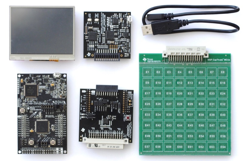
This project uses the CapTIvate MCU Development Kit as a BoosterPack and displays the pads on the Kentec 3.5" SPI screen.
The idea is to design a generic capacitive board I could use with different projects, like a board with 8 x 8 pads for a calculator. This project shows an example of a programmable sensor. Step 0: Hardware and SoftwareHardware includes (external links)
Software is available on Windows, Linux and macOS (external links) |
|
Step 1: Prepare the Hardware
|
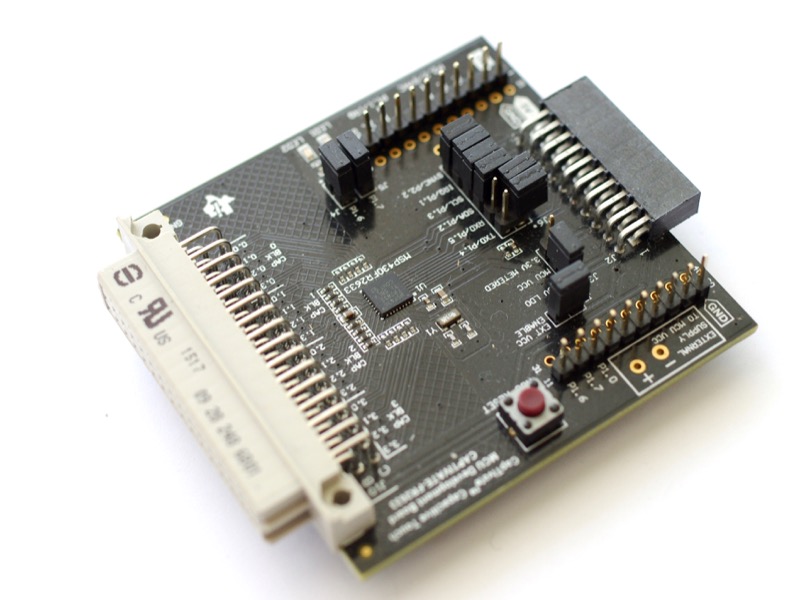
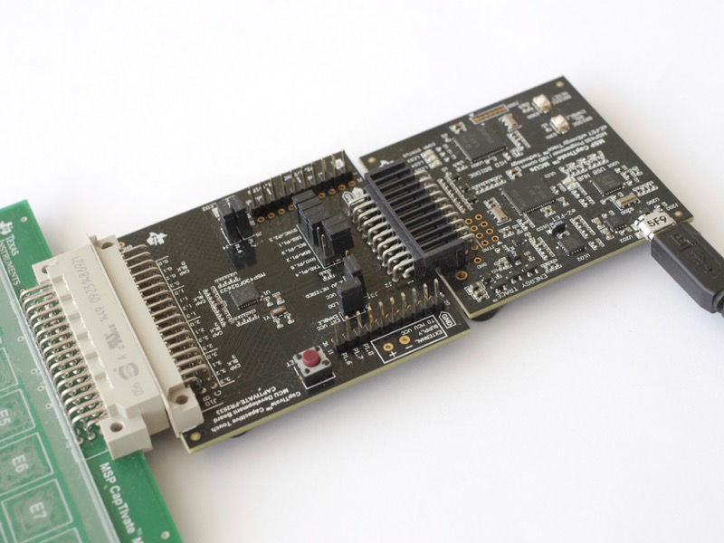
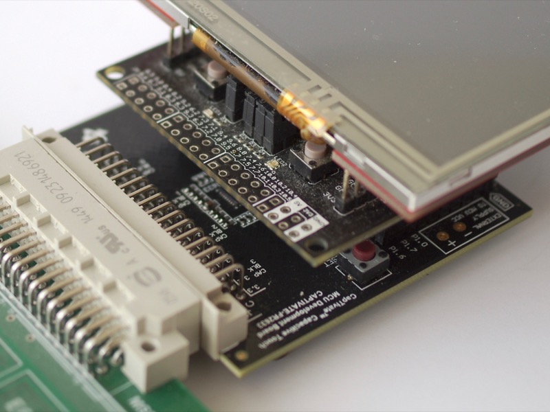
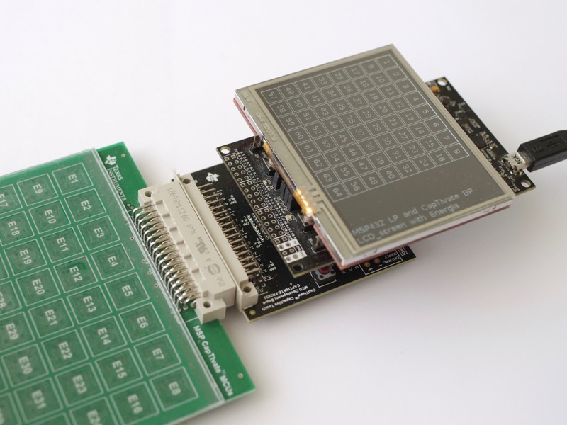
To turn the board with the MSP430FR2633 MCU into a BoosterPack, we are going to use the holes the board provisions for the extended 40-pin BoosterPack.
However, the MSP430FR2633 board only uses 20 pins, so we solder those 20 pins only. |
|
|
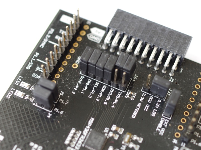
The CapTIvate board rises an interrupt on pin 8 and sends the messages in bulk, through either the UART port (pins 3 and 4) or the I²C port (pins 9 and 10).
This project uses the I²C port, so we remove the jumpers for UART, TXD/P1.4 and RXD/P1.5. This frees the UART port on the LaunchPad (pins 3 and 4) for the serial console. |
|
Step 2: Configure the BoosterPack
|
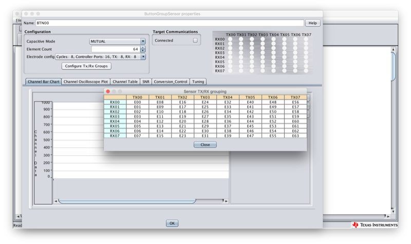
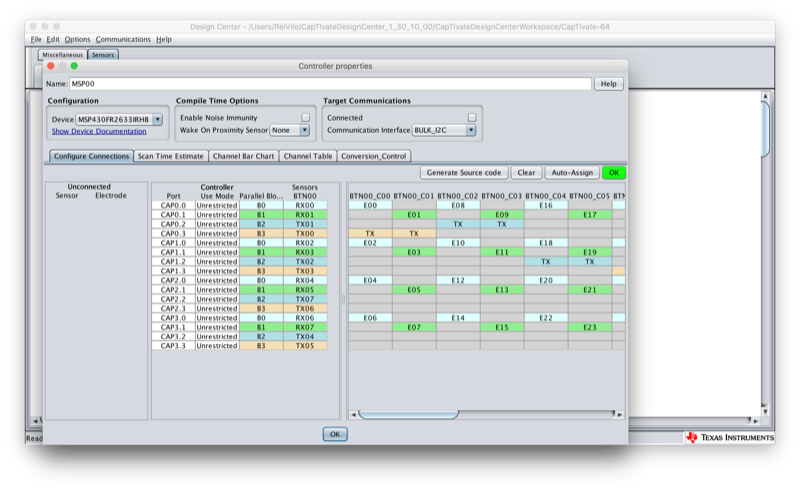
We're going to use CapTIvate Design Center GUI, available for Windows, Linux and macOS, to
Configuring a capacitive board is very easy thanks to the automatic options, one for assigning the I/O and another for generating the code. |

|
|
Let's work with CapTIvate Design Center GUI:
|
|
|
|
|
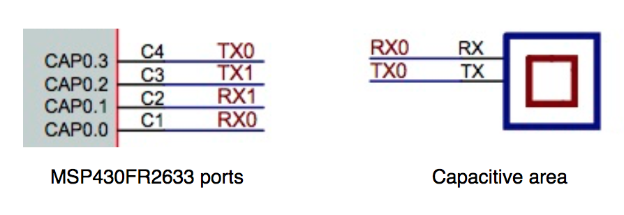
Referring to the schematics helps and improves the assignation of the elements to the TX and RX ports.
|
|
|
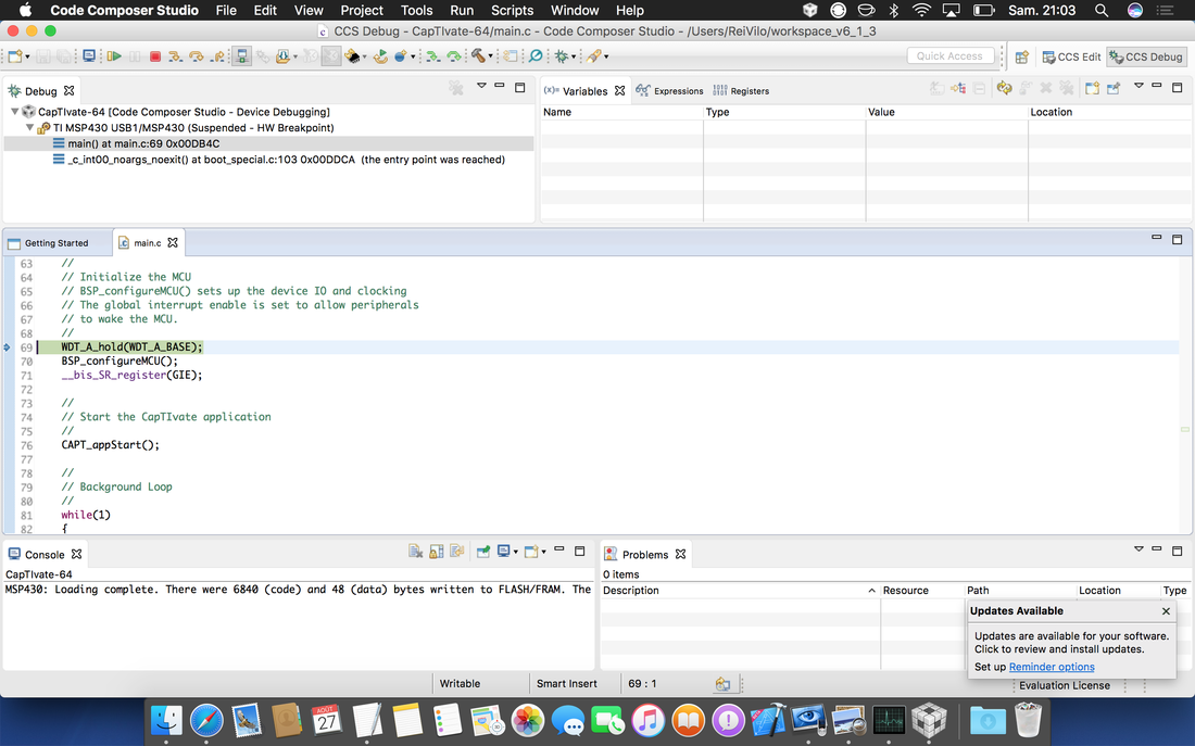
Let's work with Code Composer Studio:
|

|
|
|
|
Back to Code Composer Studio,
|
|
|
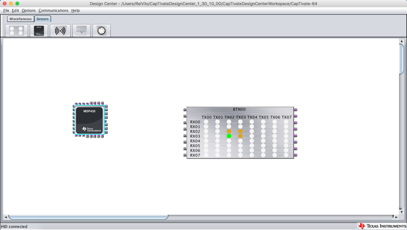
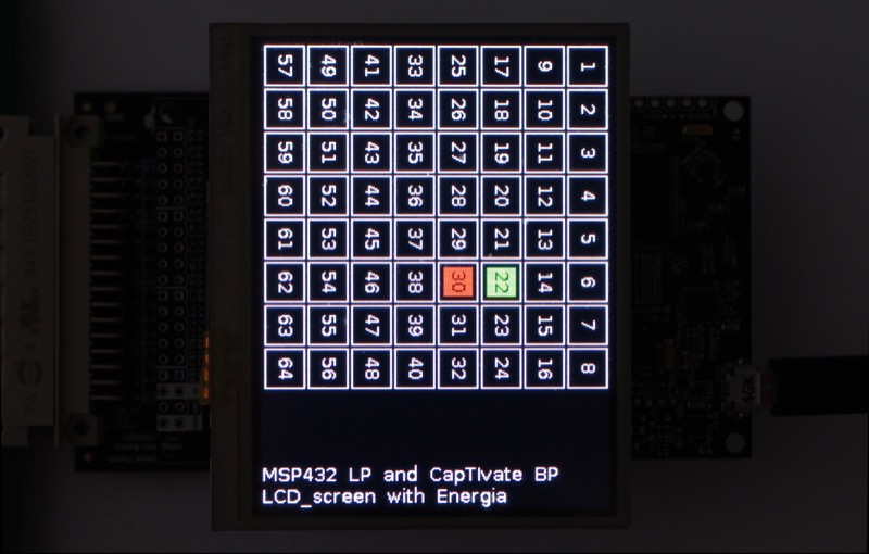
To check every works fine,
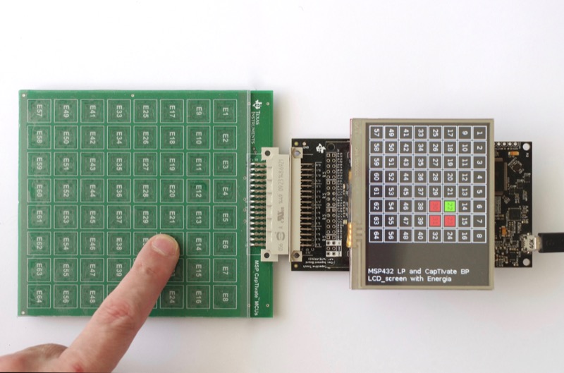
The screen shows the pads with proximity in orange and the pads with touch in green. |
|
Step 3: Program the LaunchPad
|
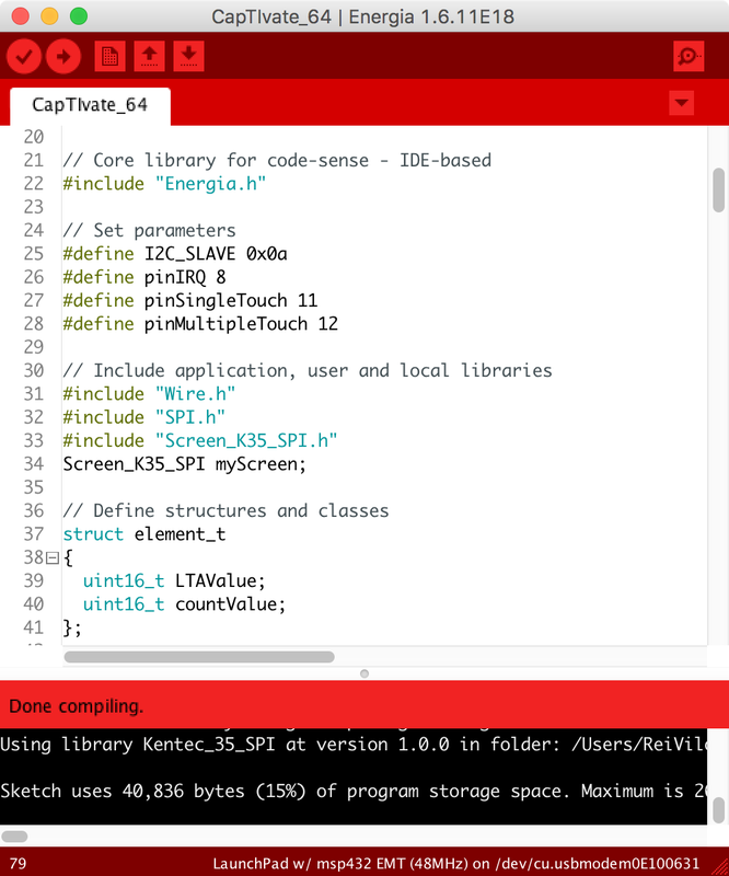
I'm using the MSP432 LaunchPad using Energia 1.6.10E18. Energia is based on the Arduino / Wiring framework. Please find the project on the right.
The project calls three libraries:
Data AcquisitionOne single function getCapTIvate64() acquires and processes the data from the BoosterPack.
The function isSomething() returns true if there is at least one pad with proximity or touch. There are five kinds of messages called packets but our project only uses the Cycle Packet, which eases reading and decoding.
Remember, the capacitive board has been configured with 1 sensor, 16 cycles of 4 elements each, for a grand total of 64 pads. |
|
|
A message includes
Texas Instruments provides all the information needed with the Technology Guide. A logic analyser was very helpful for decoding the I²C messages! |
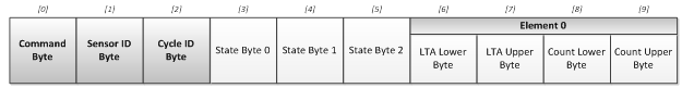
The Cycle Packet Format
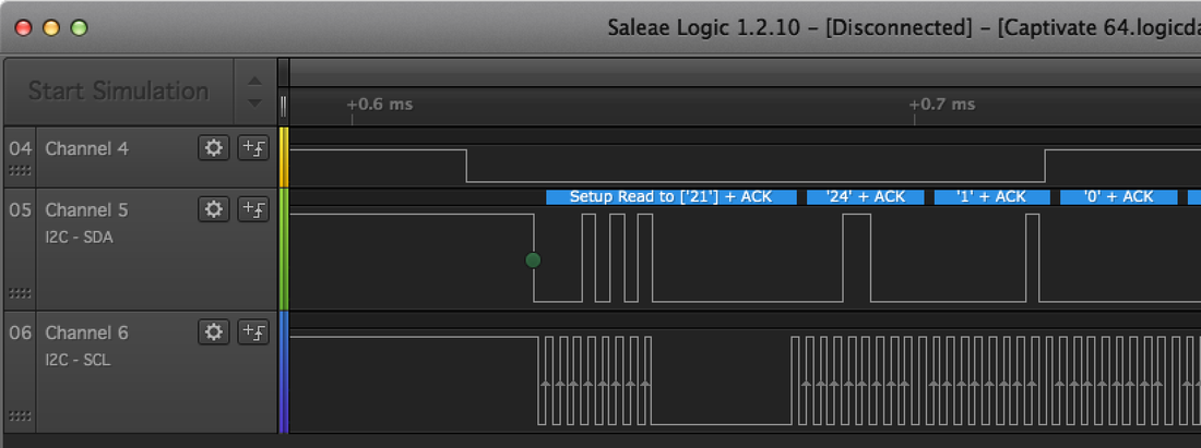
The IRQ signal and the I²C frame
|
Screen ManagementThe two functions prepareScreen() and refreshScreen() manage the screen. To speed up display, only modified areas are updated.
The screen is refreshed only
The screen shows the pads with proximity in orange and the pads with touch in green. |
|
Step 4: Build and Run the Program
|
Let's work with Energia:
|
|
Back to Energia,
|
|
|
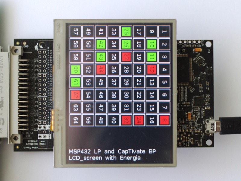
Multiple areas are displayed on the screen as CapTIvate tracks multi-touch.
The screen shows the pads with proximity in orange and the pads with touch in green. Optionally, use Code Composer Studio instead of Energia.
|
|
|
On the picture on the right, I put my left hand on the capacitive board: the board detected 8 pads with touch and 7 pads with proximity.
|
|
Conclusion
|
The CapTIvate is very efficient in sorting signal from noise, and touch from proximity.
|
|
Links |
Download
| ||
