Remote Contactless Temperature Monitor
|
How to check the temperature with no contact in COVID times? The project combines PIR detection, thermal camera and hand-gesture recognition for perfect safety. An IoT extension allows to operate it remotely.
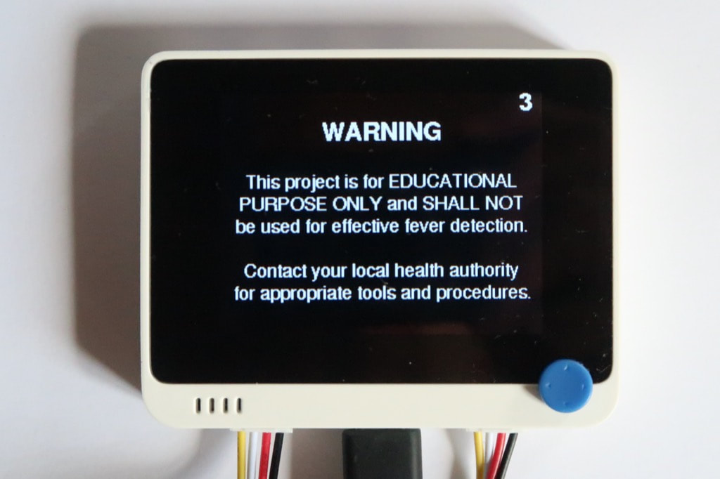
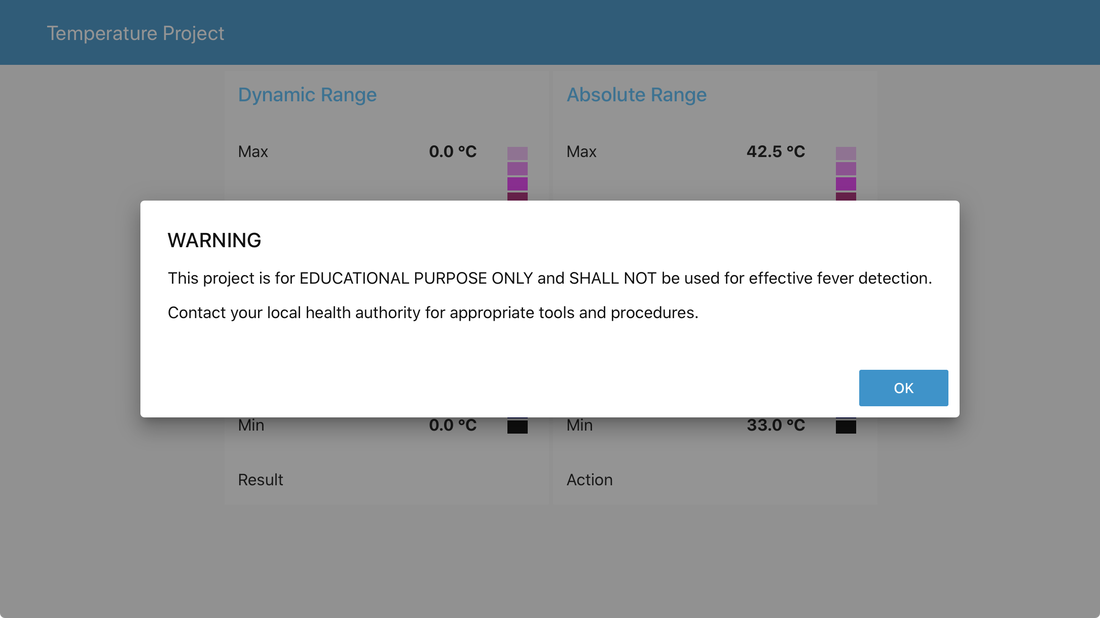
WARNING — This project is for EDUCATIONAL PURPOSE ONLY and SHALL NOT be used for effective fever detection. Contact your local health authority for appropriate tools and procedures. The hardware was sampled by SeeedStudio. |
|
How it works
|
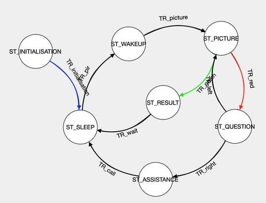
The contactless temperature monitor is built around a finite-state machine and includes seven phases.
|
After a while, the system goes back to sleep.
|
|
Prepare the hardware
|
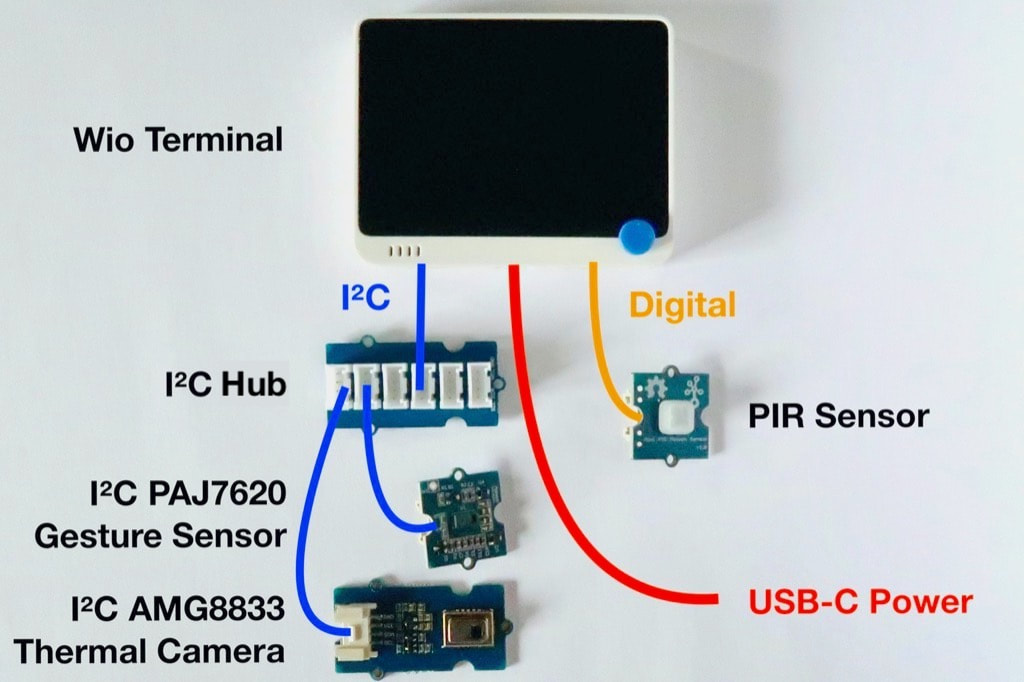
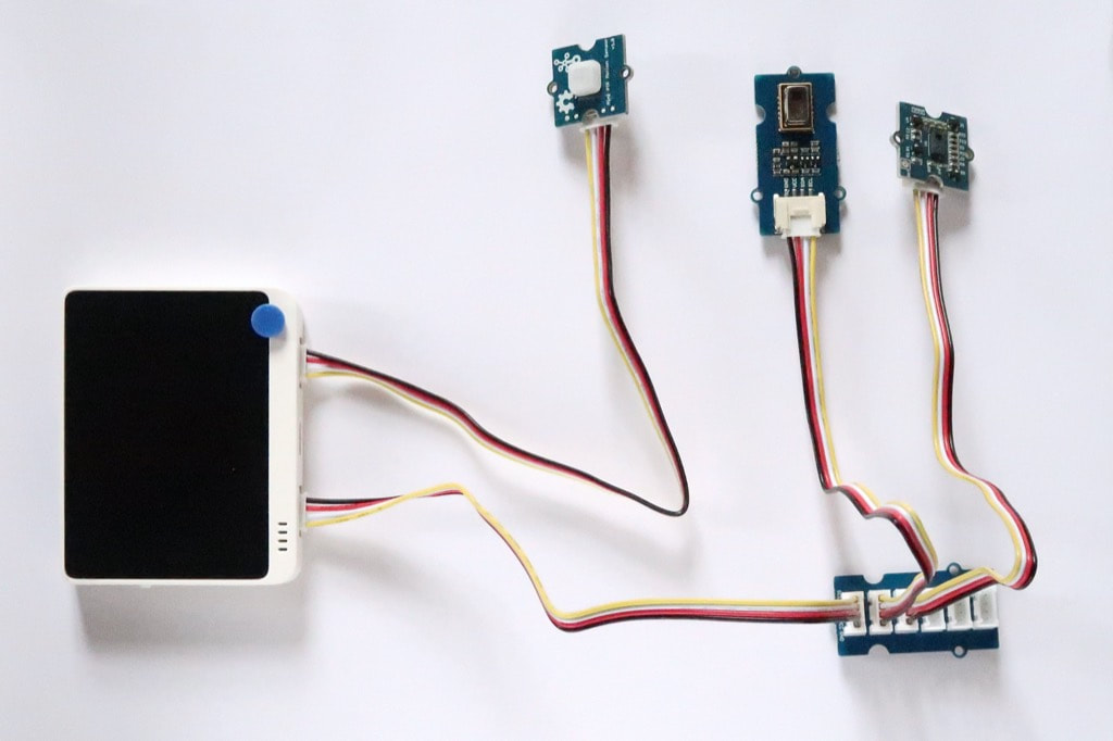
The core of the system is the Wio Terminal. It is ideally suited as it features on a compact white case a powerful MCU, a colour display, and two Grove connectors to attach the sensors.
All the sensors use the Grove connector. It provides a quick, easy and secure way to build whole applications. The IR camera and the hand-gesture sensor go to the I²C Grove connector through the I²C hub. The PIR sensor goes to the GPIO Grove connector. The Grove connectors are fool-proof and allow to build a circuit in a couple of minutes.
If you're using the Wio Terminal for the first time, you may need to go through the procedures Get Started with Wio Terminal and Update the Wireless Core Firmware.
|
|
Prepare the software
|
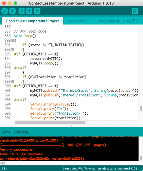
Although the project relies on the Arduino SDK, I didn't use the Arduino IDE to develop the project but embedXcode, embedded computing on Xcode, for a better productivity.
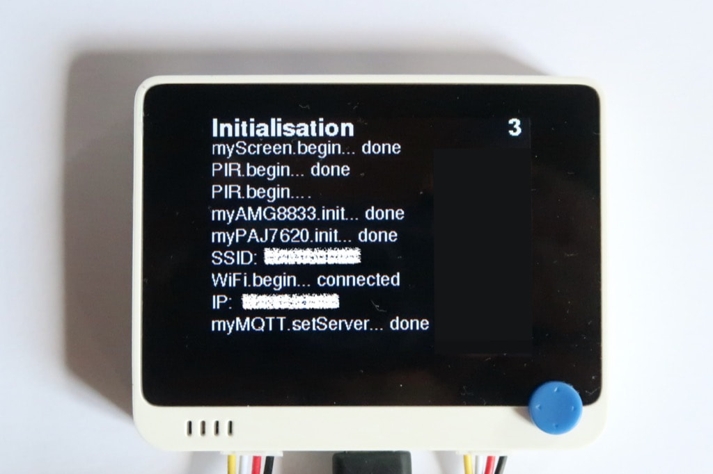
Each Grove sensor comes with its library for the Arduino SDK, and so do the screen and the WiFi radio. The project includes five sub-systems: PIR sensor, LCD display, thermal camera, hand-gesture sensor, optional WiFi for MQTT. Each sub-system was first tested separately, then integrated to the main project and fully validated before proceeding with the next one.
Each sub-system comes with a detailed wiki page: Wio Terminal, Wio Terminal WiFi, Wio Terminal screen, thermal camera, gesture sensor. The code is very basic as the project is built around a finite-state machine on the loop() function. A C++ library wraps the Gesture-PAJ7620 code as an object for better consistency. The Free_Fonts.h file lists the fonts for the 320x240 screen. The excellent PubSubClient library provides the MQTT features. The separate file Credentials.h includes the credentials for the IoT extension. |
|
How to use it
|
|
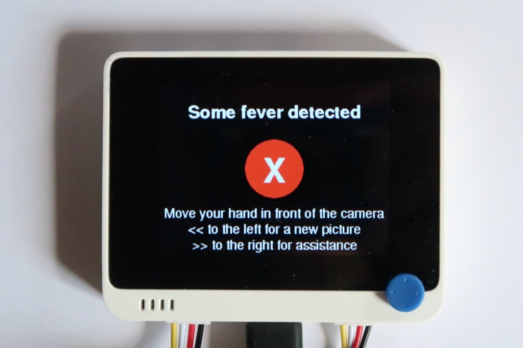
The screen displays the warning message. |
|
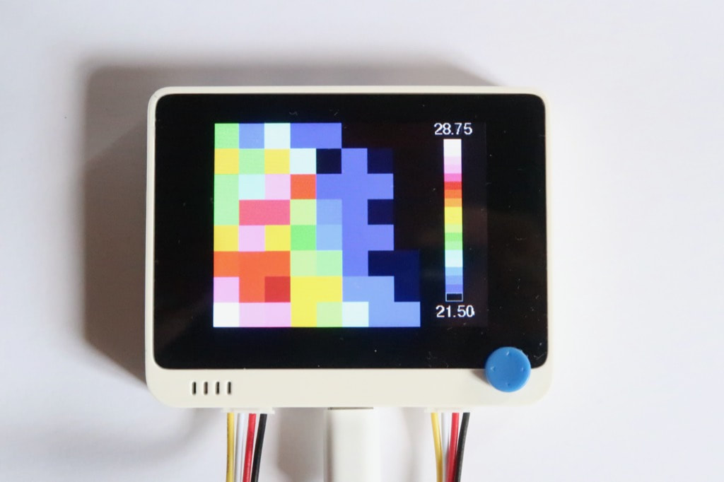
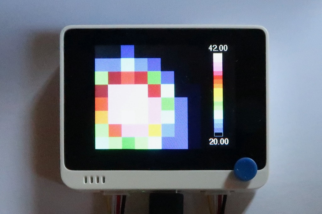
On the right side, the screen displays the scale of colours, with the minimum and maximum temperatures in °C. The picture contains 8 rows of 8 columns, or 64 pixels. A picture is considered as valid is more than three pixels have temperatures higher than 30.0 °C. For a valid picture, the test can be negative or positive based on the pixels with temperatures higher than 37,3 °C. |
|
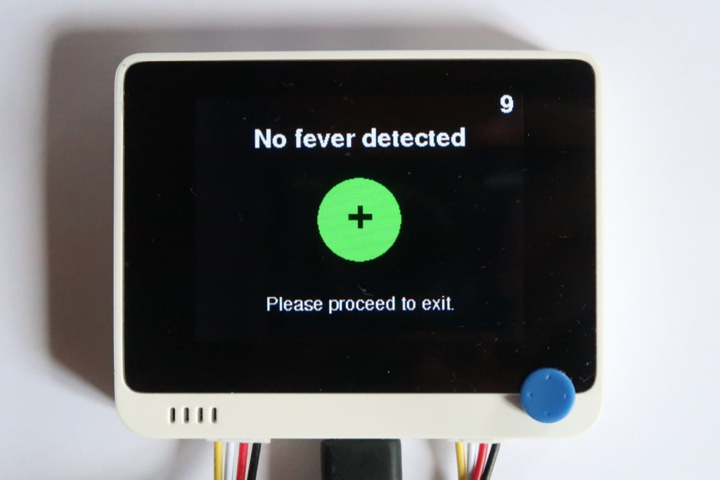
The test is considered as negative if the picture meets two criteria:
After a while, the system goes back to sleep. |
|
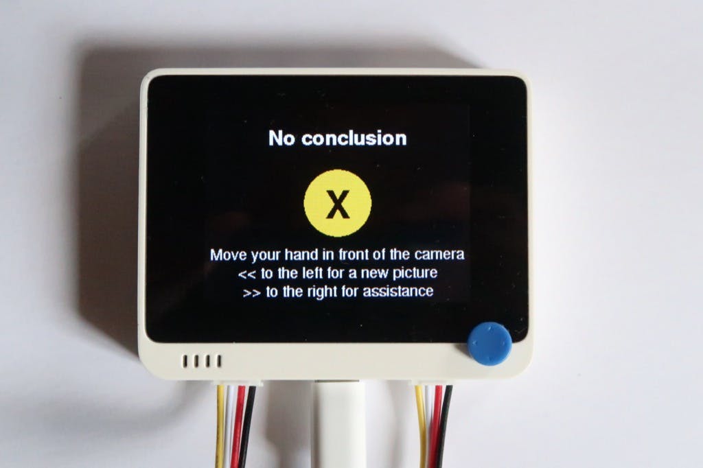
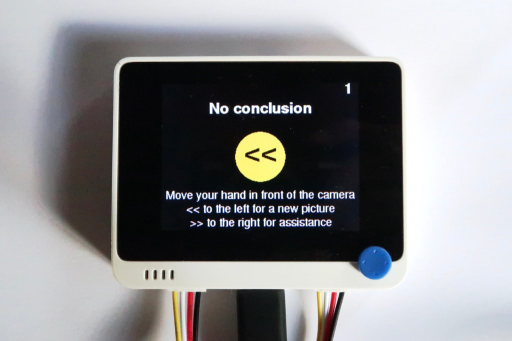
The test is considered as inconclusive if
If the previous step is inconclusive, the person is given two options: either take another picture or call for assistance. |
|
|
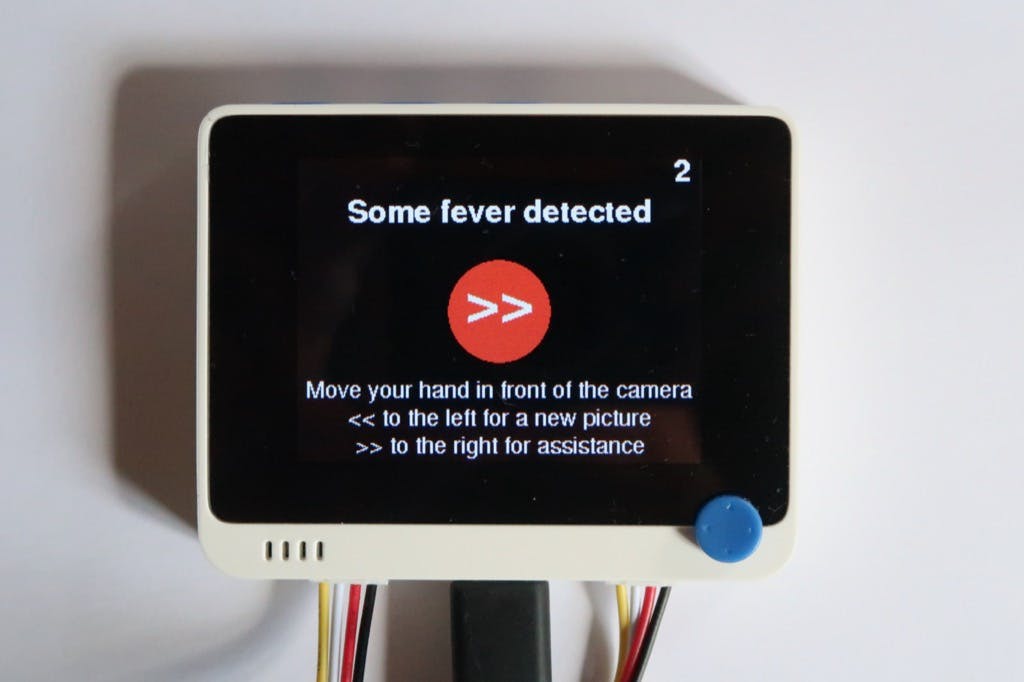
If some fever has been detected, the person is also given the same two options: either take another picture or call for assistance.
The test is considered as positive if the picture meets two criteria:
The options are displayed on the screen with the corresponding hand gestures: from right to left to take another picture, from left to right to call for assistance. |
|
|
Moving the hand to the left takes another picture.
|
|
|
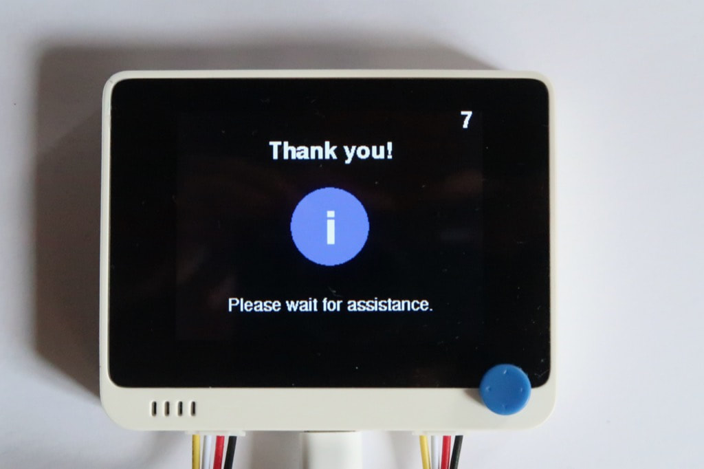
Moving the hand to the right calls the assistance.
|
|
The system then returns to low-power mode. |
|
Enable the IoT extension
|
The IoT extension relies on MQTT to connect to computer with a Node-RED server.
|
|
On a computer, for example a single board computer:
|
|
|
On the Arduino IDE,
|
|
|
|
|
|
|
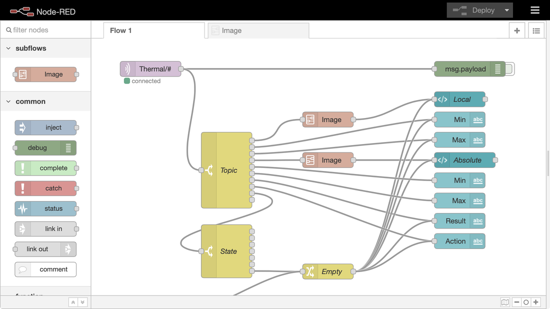
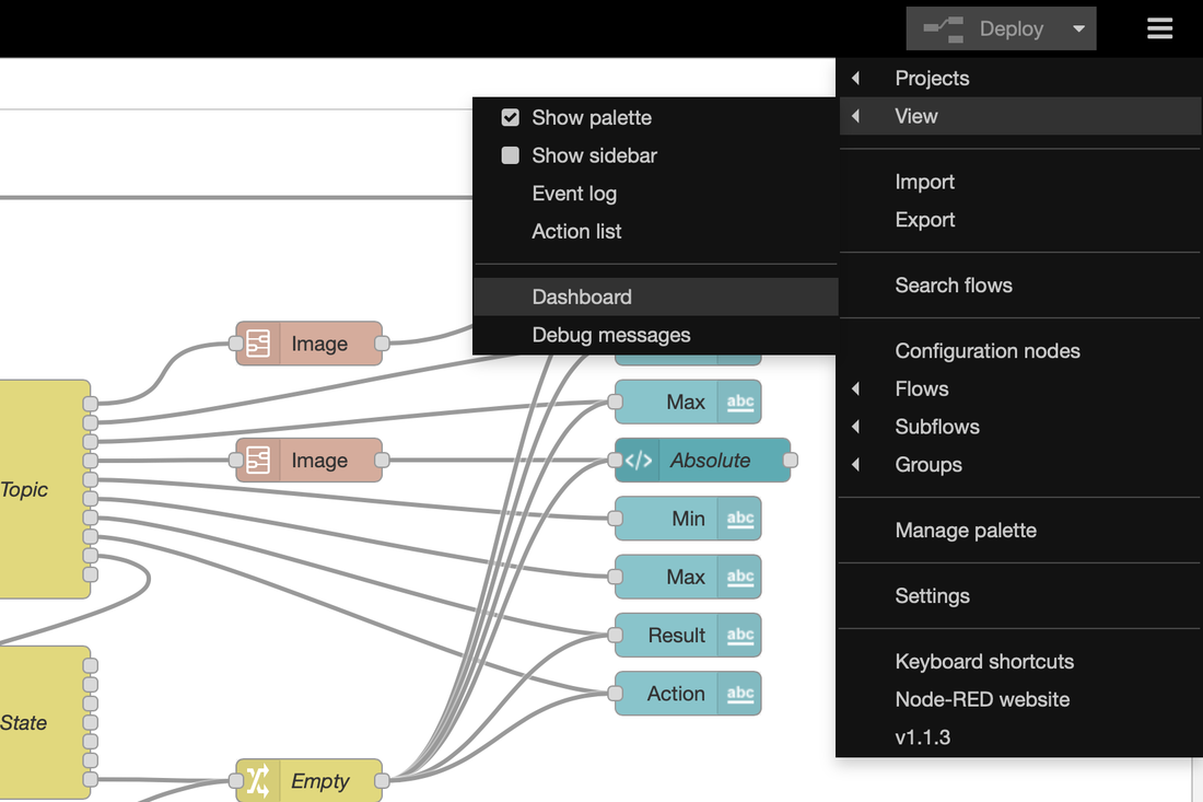
On Node-RED,
|
|
|
|
|
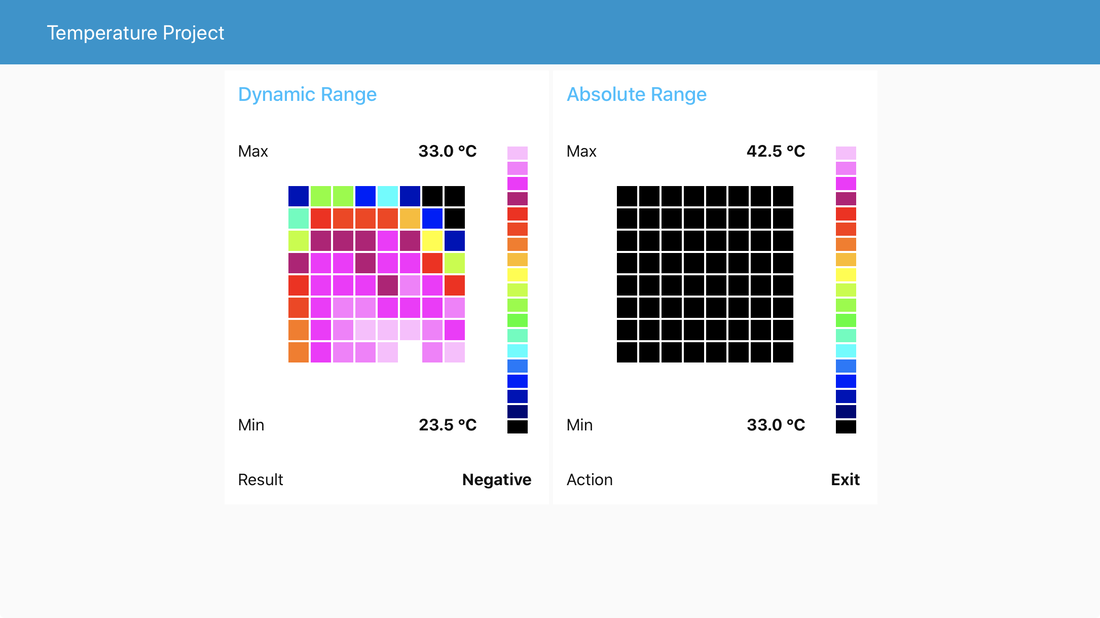
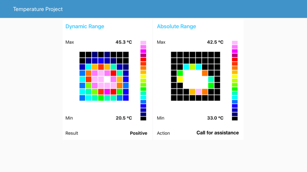
The dashboard displays two thermal pictures.
On the left, the scale is dynamic with the lowest and highest temperatures to define the range. Here, the highest temperatures is 33.0 °C, which is safe. On the right, the scale is absolute from 33.0 to 42.5 °C. The threshold is set at 37.5 °C: lime is just below 37.5 °C and yellow just above. |
|
|
Here, a cup of tea simulates a positive case.
|
|
|
The two thermal pictures with different ranges and scales help the staff decide what to do.
Finally, two more fields give the result and recommended action. When action displays Call for assistance, the person is waiting for the staff. |
|
Improve the local display
|
By default, the image displayed has the same resolution as the thermal sensor, or 8x8 resolution.
The initial image is resampled through a bi-cubic interpolation to provide a nicer picture, here in 16x16 resolution. The FPU of the ATSAMD51 manages all the computations required by the interpolation effortlessly. |
|
Conclusion
|
The Wio Terminal handles it all: data acquisition and processing, display and WiFi communication with standard MQTT protocol. The Grove connectors are safe and quick to use to connect all the sensors, either I²C or digital.
Below are some ideas to refine the project and add new features. |
|
Going further
|
The selected IR camera provides a 8x8 matrix with ±2.5°C accuracy. Better resolution and accuracy can be achieved with other Grove thermal cameras like the Grove Thermal Imaging Camera - MLX90621 BAA 16x4 IR Array with 25° FOV (±1°C ±3% accuracy), the Grove - Thermal Imaging Camera - MLX90641 BCA 16x12 IR Array with 110° FOV (±1.5℃ accuracy), or the Grove - Thermal Imaging Camera - MLX90640 32x24 IR Array with 110° FOV (±1.5℃ accuracy).
The entire system can run on batteries with the Wio Terminal Battery Chassis - Built-in 650mAH Lithium Battery with 6 Grove Interfaces. On the IoT side, the project relies on MQTT and Node-RED with a local router. Other options include adding messages sent from the dashboard to the Wio Terminal screen, using an external MQTT broker like HiveMQ, turning WiFi as an access point to provide a private LAN, relying on other protocols like CoAPand on a third-party service like IFTTT or Blynk. Also to be considered, an OTA update of the firmware for easier maintenance. |
The same thermal picture, clockwise from top-left: original image 8x8, oversampled bi-cubic images 16x16, 24x24 and 32x32
|
Links

Posted: 24 Aug 2020
Updated:
