Connecting the Pervasive Displays EXT3-1
|
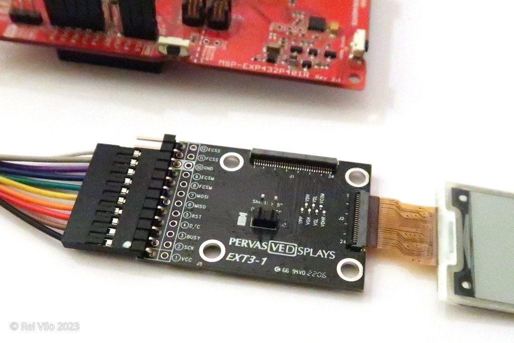
Compared to initial Pervasive Displays e-Paper EPD Extension Kit Gen 3, the first revision simplifies the connections with a 10-way cable and supports an optional board for touch.
The 10-way cable still uses the standard electronics colours to ease the identification of each signal, speed up the connection and limit the errors |
|
Connecting the EXT3-1 to the screen
|
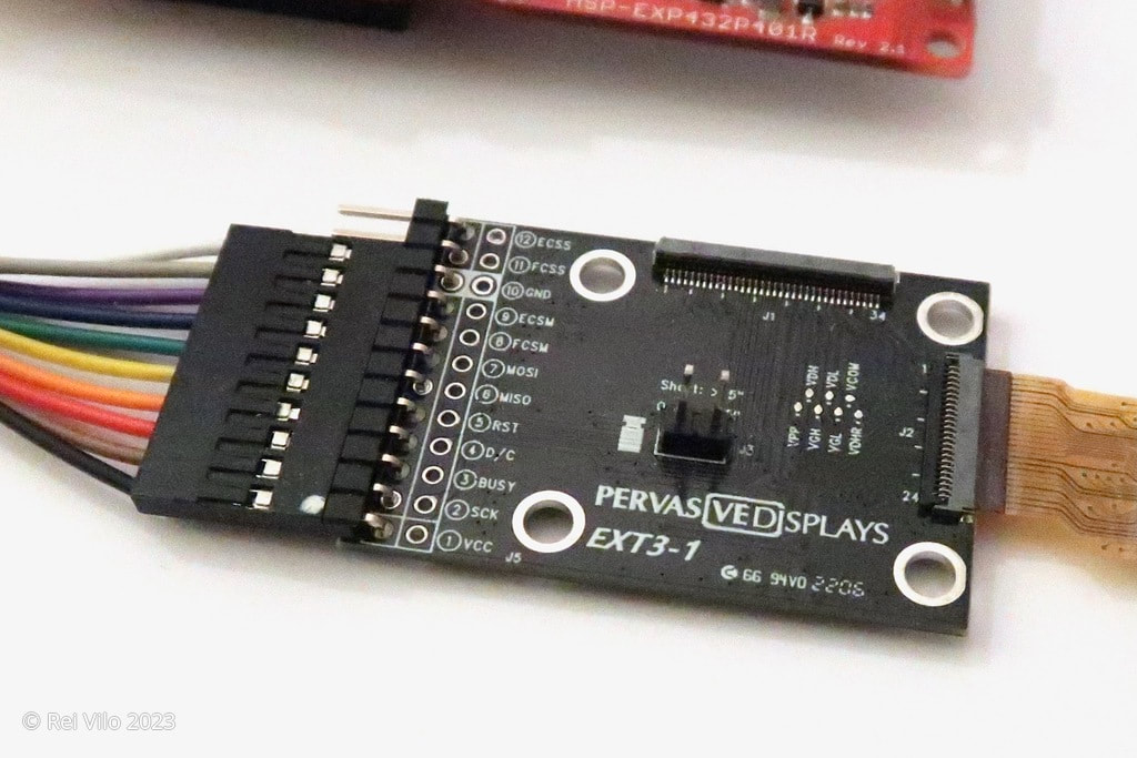
The Extension Kit Gen 3-1 features two connectors for flat cables:
Gently lift the lock up, insert the flat cable and replace the lock back. Only one screen can be attached at a time. The final step is the jumper for the inductance.
On the example shown on the right, a 24-way flat cable is attached and there is no jumper for a screen smaller than 4.37".
|
|
Connecting the EXT3-1 to the micro-controller
|
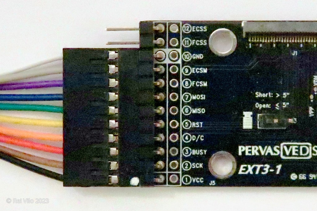
To connect the EXT3-1 to the micro-controller, plug the 10-way cable into the male pins of the EXT3-1 board with
The remaining two male pins of the EXT3-1 board are optional and used in the following two cases:
Plug the 2-way cable into the remaining two male pins of the EXT3-1 board. |
|
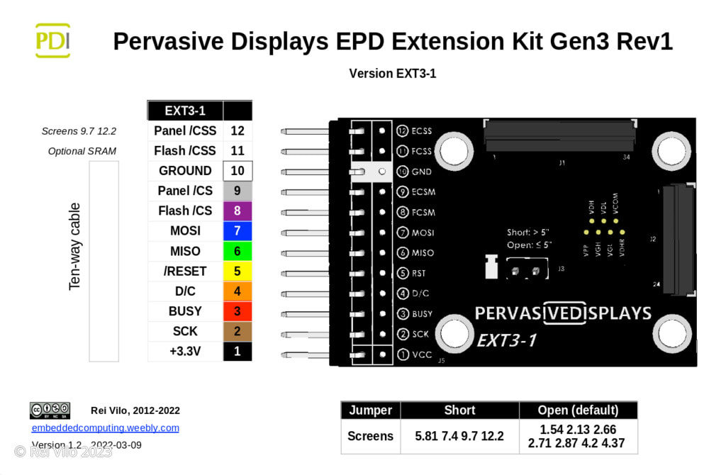
All the signals are detailed below. Note that that pins 11 and 12 are optional.
|
On the micro-controller side, only the top part of the 20-way cable numbered 1 through 10 is going to be connected:
|
Power and logic signals are 3.3V only. Connecting the EXT3 to 5V may damage the board and the screen. A regulator and logic level converters are required. |
|
The connections for the other cables are specific to each board.
On the sofware side, the hV_Configuration.h file of the ePaper_EXT3_Basic_Library (link 1, link 2) lists those configurations. To select a given board, just use the board name to the screen constructor, here for boardLaunchPad. On the hardware side, the following sections provide the configurations for the most popular boards:
|
hV_Configuration.h
|
Posted: 08 Feb 2023
Updated:
